Fire & Smoke Damper Actuators
Fire & Smoke Damper Actuators
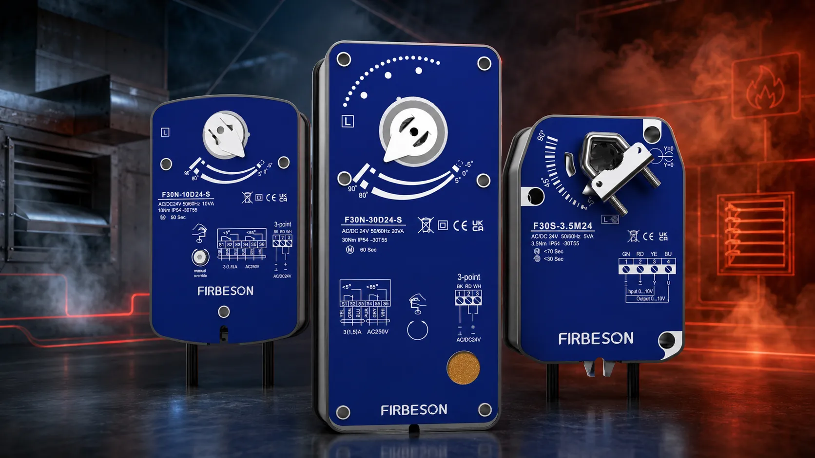
Actuators for applications where damper position must be guaranteed under emergency conditions. The range covers fire compartmentation, smoke extraction and fail-safe ventilation control, with torque ratings from 3.5 Nm to 20 Nm. Three series are available: F30S spring return for general fail-safe duties, F30F spring return with fire and smoke features including an optional 72 °C thermal sensor, and F30N non-spring return for higher torque smoke damper installations.
Choosing Your Series
| F30S Spring Return | F30F Fire & Smoke | F30N Non-Spring Return | |
|---|---|---|---|
| Torque | 3.5–20 Nm | 3.5–20 Nm | 10–40 Nm |
| Fail-safe method | Spring return | Spring return | None |
| Spring return time | <20–30 s | <20–30 s | — |
| Thermal sensor option | — | 72 °C, ambient & duct | — |
| Auxiliary switches | Optional 2 SPDT | 2 SPDT | 2 SPDT |
| Control | 2-point or 0(2)–10 V | 2-point or 0–10 V | 2/3 point |
| Ambient temperature | −30 to +55 °C | −30 to +55 °C, Max safe Temperature: 75°C | −30 to +55 °C, Max safe Temperature: 75°C |
| Certification | CE, UKCA, UL, RoHS | CE, UKCA, UL, RoHS | CE, UKCA, UL, RoHS |
F30S Series Spring Return Damper Actuator
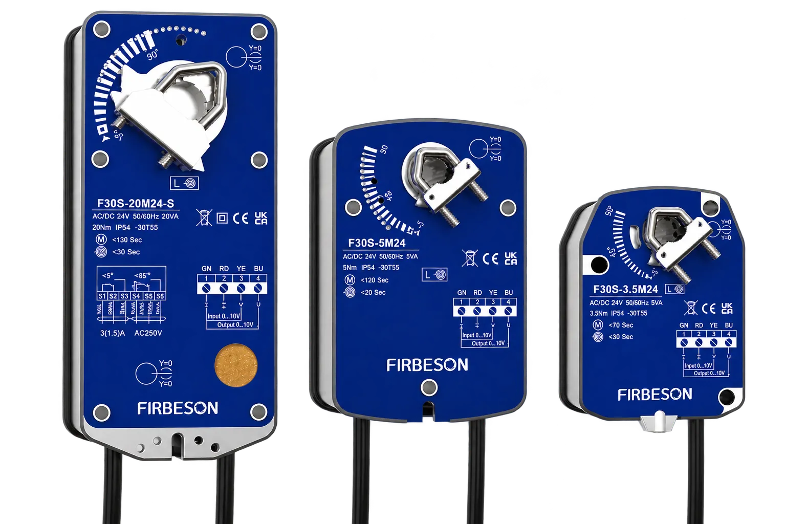
Spring return actuators for applications requiring a defined fail-safe position. A charged spring drives the damper back to its predetermined position on loss of power or control signal, without relying on the motor or an external supply. Suited to fire and smoke compartmentation, fresh air intakes, and frost protection duties.
Find out more technical details about our F30S
Torque and Running Time
| Torque | Damper area | Motor running | Spring return | Weight |
|---|---|---|---|---|
| 3.5 Nm | 0.8 m² | <70 s | <30 s | 1.0 kg |
| 5 Nm | 1 m² | <70 s | <20 s | 1.4 kg |
| 10 Nm | 2 m² | <100 s | <30 s | 2.4 kg |
| 15 Nm | 3 m² | <130 s | <30 s | 2.4 kg |
| 20 Nm | 4 m² | <130 s | <30 s | 2.4 kg |
Modulating models run slower: motor running <120 s on 5 Nm and 10 Nm units.
Specification
- Supply voltage: AC/DC 24 V (19.2–28.8 V) or AC 230 V (85–265 V), 50/60 Hz
- Control: 2-point, or modulating 0(2)–10 V
- Power consumption: 2.5–7 W in operation, 1.6–2.5 W holding
- Angle of rotation: 0–90° (max 93°), L/R switchable
- Position feedback: None or 2 SPDT
- Noise level: 50 dB running, 62 dB spring return
- Protection: IP54, class II/III
- Ambient: −30 to +55 °C, 5–95% RH
- Life cycle: ≥70,000
- Spindle: 8–14 mm (3.5 Nm) · 10–16 mm (5 Nm) · 12–20 mm (10–20 Nm)
- Certification: CE, UKCA, UL, RoHS
Order Code
F30S – [torque] [control] [voltage] – [accessory]
Control: D = 2-point, M = modulating. Voltage: 24 = AC/DC 24 V, 230 = AC 85–265 V. Accessory: S = auxiliary switches.
Example: F30S-10D24-S — 10 Nm, 2-point, 24 V, with auxiliary switches.
F30F Series Fire & Smoke Damper Actuator
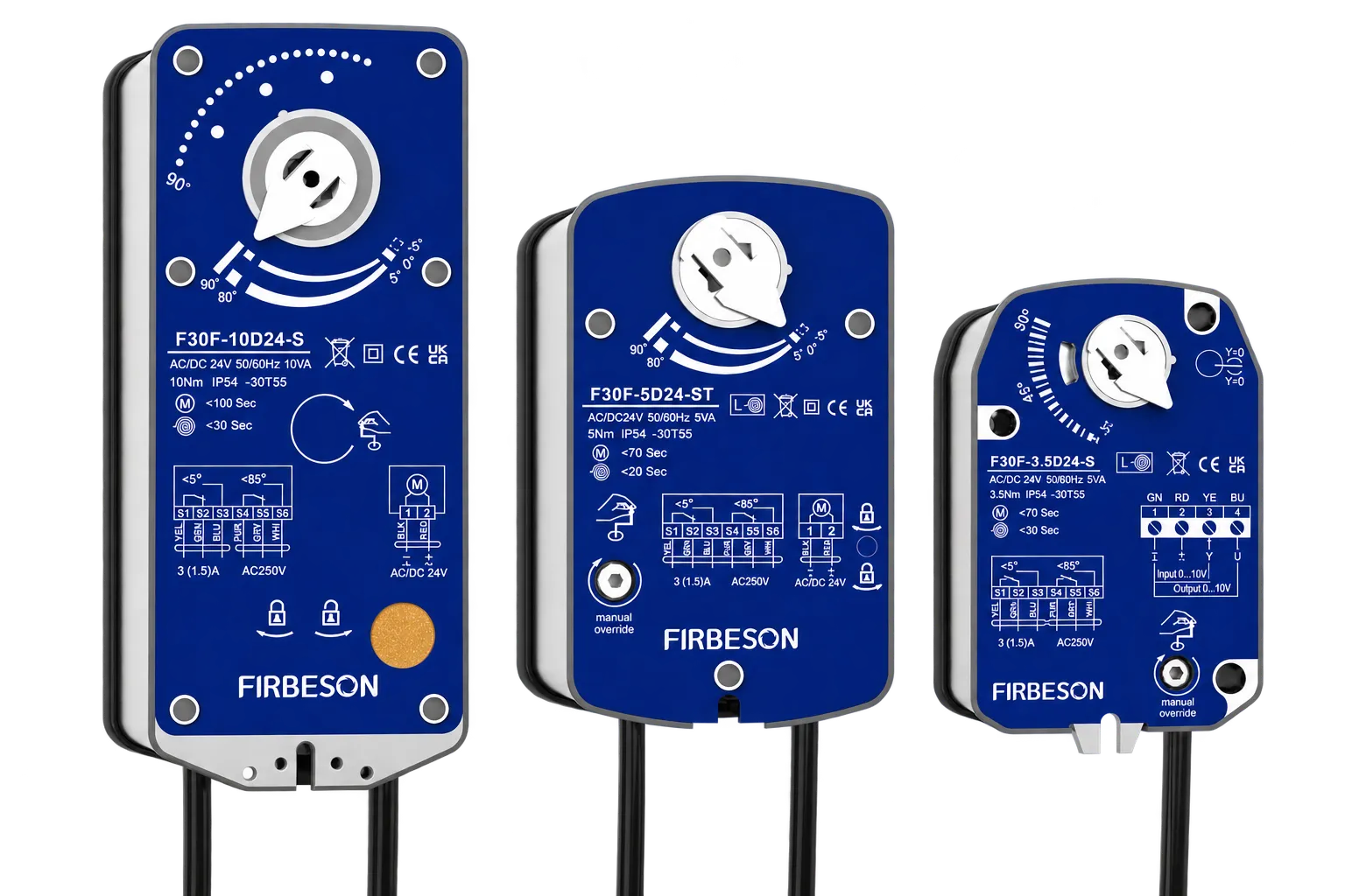
Spring return actuators built specifically for fire and smoke damper duties. Two SPDT auxiliary switches are fitted as standard for position feedback to the fire alarm or building management system, and an optional 72 °C thermal sensor provides independent over-temperature closure. A manual override with locking key allows the damper to be set and held during commissioning and periodic testing.
Find out more technical details about our F30F
Torque and Running Time
| Torque | Damper area | Motor running | Spring return | Weight |
|---|---|---|---|---|
| 3.5 Nm | 0.8 m² | <70 s | <30 s | 1.2 kg |
| 5 Nm | 1 m² | <70 s | <20 s | 1.6 kg |
| 10 Nm | 2 m² | <100 s | <30 s | 2.6 kg |
| 15 Nm | 3 m² | <130 s | <30 s | 2.6 kg |
| 20 Nm | 4 m² | <130 s | <30 s | 2.6 kg |
Modulating models run slower: motor running <120 s on 5 Nm and 10 Nm units.
Specification
- Supply voltage: AC/DC 24 V (19.2–28.8 V) or AC 230 V (85–265 V), 50/60 Hz
- Control: on/off 2/3 point, or modulating 0–10 V
- Power consumption: 2.5–7 W in operation, 1.6–2.5 W holding
- Angle of rotation: 0–90° (max 93°), L/R switchable
- Position feedback: 2 SPDT fitted as standard
- Noise level: 50 dB running, 62 dB spring return
- Protection: IP54, class II/III
- Ambient: −30 to +55 °C, maximum safe operating temperature 75 °C
- Life cycle: ≥70,000
- Spindle: 10×10 mm or 12×12 mm square
- Certification: CE, UKCA, UL, RoHS
72 °C Thermal Sensor (ST models)
The optional thermal sensor comprises two probes operating independently of the control system:
- TS1 — ambient probe: disconnects when the surrounding air temperature exceeds 72 °C
- TS2 — duct probe: disconnects when the duct temperature exceeds 72 °C
Either probe disconnecting removes the supply to the actuator, releasing the spring and closing the damper regardless of the signal from the control system.
Order Code
F30F – [torque] [control] [voltage] – [accessory]
Control: D = on/off, M = modulating. Voltage: 24 = AC/DC 24 V, 230 = AC 85–265 V. Accessory: S = auxiliary switches, ST = auxiliary switches plus thermal sensor.
Example: F30F-10D24-ST — 10 Nm, on/off, 24 V, with auxiliary switches and thermal sensor.
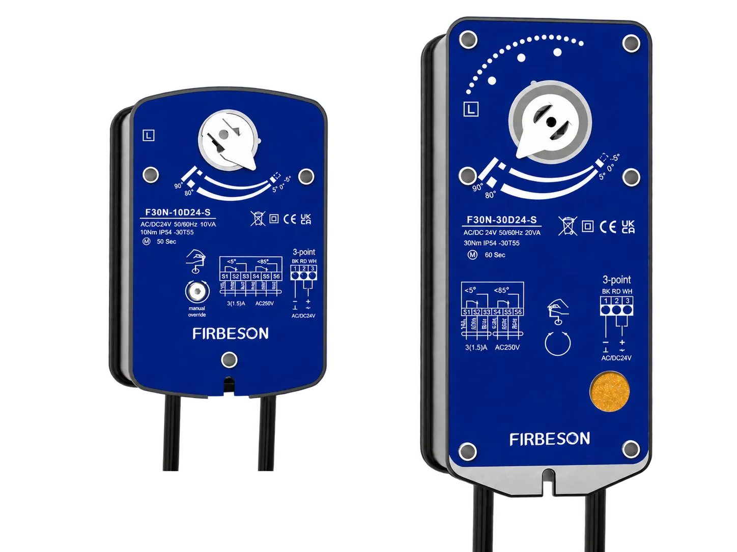
F30N Series Non-Spring Return Smoke Damper Actuator
Non-spring return actuators for larger smoke damper installations, covering higher torque duties from 10 Nm to 40 Nm where a motorised return is specified in place of a spring. Two SPDT auxiliary switches are fitted as standard, and a manual override allows the damper to be positioned by hand during commissioning.
Find out more technical details about our F30N
Torque and Running Time
| Torque | Damper area | Running time | Power (on) | Weight |
|---|---|---|---|---|
| 10 Nm | 2 m² | 50 s | 3 W | 1.5 kg |
| 15 Nm | 3 m² | 50 s | 5 W | 1.5 kg |
| 30 Nm | 6 m² | 60 s | 6 W | 2.0 kg |
| 40 Nm | 8 m² | 60 s | 6.5 W | 2.0 kg |
Specification
- Supply voltage: AC/DC 24 V (19.2–28.8 V) or AC 230 V (85–265 V), 50/60 Hz
- Control: on/off, 2/3 point
- Power consumption: 3–6.5 W in operation, 1 W at rest
- Angle of rotation: 0–90° (max 93°), L/R switchable
- Position feedback: 2 SPDT fitted as standard
- Noise level: 50 dB
- Protection: IP54, class II/III
- Ambient: −30 to +55 °C, maximum safe operating temperature 75 °C
- Life cycle: ≥70,000
- Spindle: 10×10 mm or 12×12 mm square
- Certification: CE, UKCA, UL, RoHS
Order Code
F30N – [torque] [control] [voltage] – [accessory]
Control: D = on/off. Voltage: 24 = AC/DC 24 V, 230 = AC 85–265 V. Accessory: S = auxiliary switches.
Example: F30N-30D24-S — 30 Nm, on/off, 24 V, with auxiliary switches.
Auxiliary Switches
Auxiliary switches provide volt-free position feedback to the fire alarm panel or building management system, confirming that the damper has reached the open or closed position.
- Rating: 3(1.5) A at AC 250 V
- Switching points: <5° and <85° of travel
- Configuration: two SPDT contacts (F30F and F30N standard, F30S optional)
Manual Operation
F30F and F30N actuators can be positioned by hand for commissioning and periodic testing:
- Insert the handle into the hexagon socket on the actuator.
- Turn evenly and slowly in the direction shown on the product label. The output shaft rotates with the handle.
- Once at the desired position, turn the locking key 90° in the direction indicated. The output shaft is now locked.
- To release, turn the locking key back once more.
⚠ Do not attempt manual operation while the actuator is undergoing rapid spring rebound. Doing so may prevent the manual position being secured and can damage internal components. Never use power tools in place of the handle.
Installation
- Rotate the damper shaft to the fully closed position before fitting.
- Fit the actuator onto the damper shaft, selecting L or R side mounting as required.
- Attach the mounting bracket to the rear of the actuator and secure with self-tapping screws, allowing 40–50 mm clearance.
- Tighten the output shaft nut clockwise — 9 Nm on F30S units.
- Adjust the output angle limit by repositioning the limit block with a screwdriver.
- Fit the thermal sensor probes where specified (ST models).
- Wire according to model.
⚠ Installation must be carried out by personnel with relevant training or work experience. Do not work on the actuator with the supply live. Spring return actuators store mechanical energy — do not dismantle the unit or attempt repair on site. Install in accordance with applicable regulations.
Testing and Maintenance
Fire and smoke dampers require periodic testing to confirm they operate correctly under fault conditions. Auxiliary switch feedback allows drop tests to be verified at the control panel without accessing the damper. Refer to the operational manual for the recommended test procedure, and carry out testing in line with the applicable building regulations and the damper manufacturer's instructions.
Find out more about wiring and dimensions for our F30S/F/N